Enterprise Network Project
In this post, I’ll walk through a two-office enterprise network project I designed using the 3-Tier Network Architecture. The scenario is as follows:
A company has two offices: Office A and Office B. Each office has multiple departments isolated into their own VLANs. The network is designed with a three-tier architecture, using dual Core and Distribution switches. Both offices are buildings on the same site, connected by fiber, and Office B is the main building that houses the core, the servers and the internet edge. At this size a collapsed core would be enough. I chose the three-tier design on purpose to show a real network design and it leaves room to add another building without touching the existing ones. In the next chapters, I’ll explain in detail how I designed and configured this network from scratch. I will also explain the reasons behind configuration decisions. All configuration files, diagrams and notes are available on https://github.com/mvltblt/network-configurations/tree/main
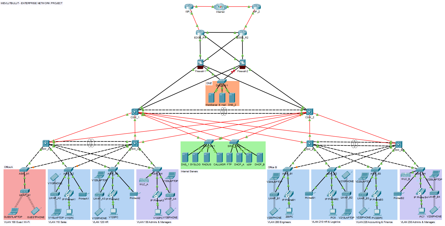
Part 1 - Setup
Initial Configuration
The first step is configuring the matching hostnames on each device as shown in the diagram. Before configuring an enable secret on each device, I used the enable secret ? command to check the supported hashing types. Routers and Access Switches support type 5 hashing (MD5), while Distribution and Core Switches support type 9 (scrypt). Firewalls only support enable password, because ASA hashes automatically using a strong algorithm (PBKDF2). Unlike IOS devices, there’s no manual hash-type selection here.
To avoid repetition, I’ll only give one example per scenario. Same logic applies to similar devices depending on the scenario.
Routers and Access Switches:

Distribution and Core Switches:
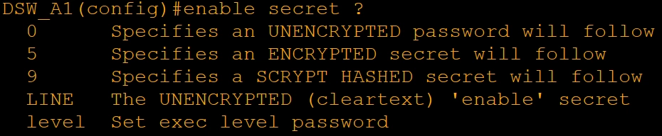
Firewalls:

On each device, except firewalls, an enable secret of “1234” (lab only) was configured using the highest available hashing type. User accounts with the username “cisco” and a secret of “password” (lab only) were set up using the highest hashing type available.
Unlike IOS devices, ASA firewalls don’t have the line console 0 model. Because of this, local authentication for console and SSH access is enforced through AAA, which I will cover in a later section together with the SSH setup. At this stage, only the hostname, enable password and local user account were configured on the firewalls.
A 15-minute inactivity timeout was also configured for security on the IOS-based devices, along with synchronous logging for convenience. You can find all of the commands for each device on GitHub.
Part 2 - VLANs, Trunk Links and L2 EtherChannels
VLANs
This section explains the VLAN structure for the network. IP addressing and subnetting are covered in the following parts.
The company has two offices, each with departments segmented into dedicated VLANs. The design also includes infrastructure VLANs that support network wide functions rather than a specific department, as listed below.
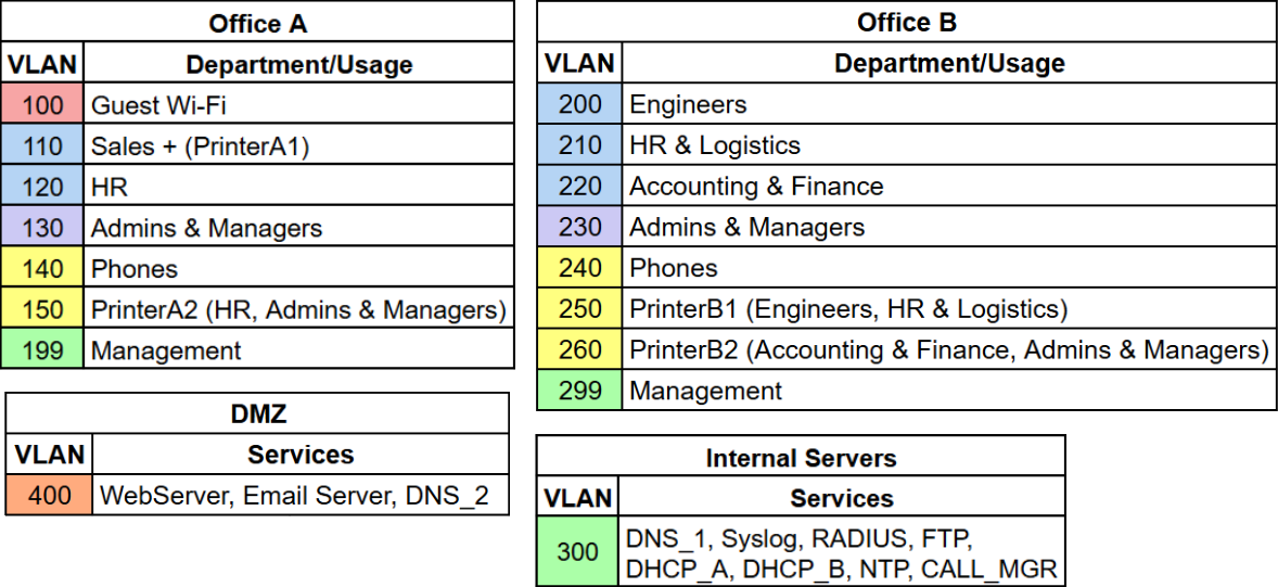
Apart from the VLANs above, two other VLANs exist in this design that are not shown in the table. VLAN 999 is used exclusively to disable unused ports. VLAN 998 is associated with OSPF and will be covered in the OSPF section below.
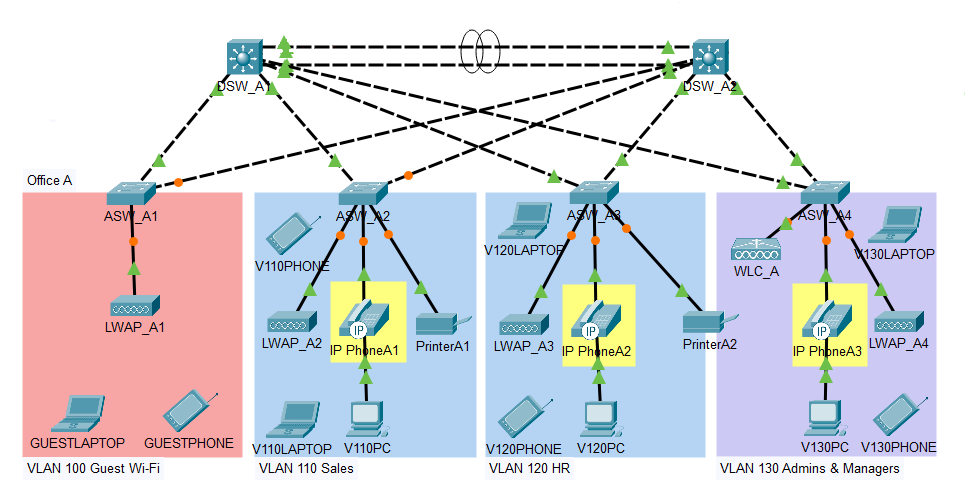
Before the configuration of VLANs on Access switches part, I would like to explain the colors I used in the diagram. Initially, I wanted to use different colors for each VLAN. However, it became impossible due to excessive amounts of colors that would complicate the diagram. For this reason, VLANs were grouped according to their trust zone. This reduced the number of colors to 6.
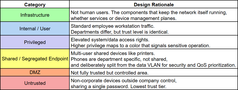
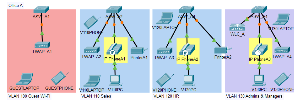
To keep this writing from becoming unnecessarily long, I will walk through Office A because the same logic works for Office B. The device icons in the diagram are symbolic and don’t show the exact number of devices, which is listed in the IP addressing section.
In the diagram each VLAN is colored by its trust zone from the table above. PrinterA1 is not inside a cube because PrinterA1 is a dedicated printer for the Sales department, unlike PrinterA2, which is shared across departments. The phones’ and laptops’ Wi‑Fi connections are not shown here and will be covered in the Wireless part.
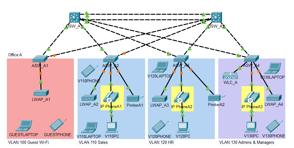
Each Access switch was connected to both Distribution switches to provide redundancy, following standard three-tier architecture design.
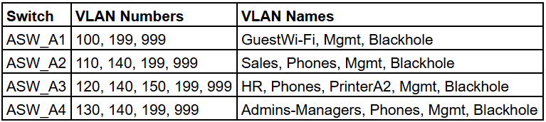
In Office A, VLANs are configured on each switch as shown below:
Trunk Links
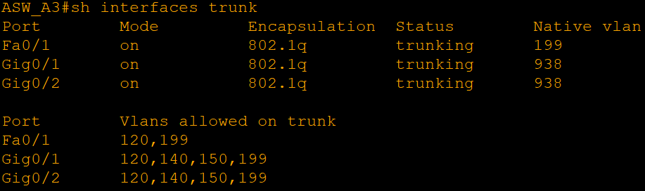
The connection from both Access and Distribution switches has been configured into trunk ports, with the native VLAN being randomly selected (VLAN 938), in order to avoid the VLAN hopping attack. Disabling the DTP on all interfaces is recommended as best practice, though the access interface will never become a trunk port through negotiation.
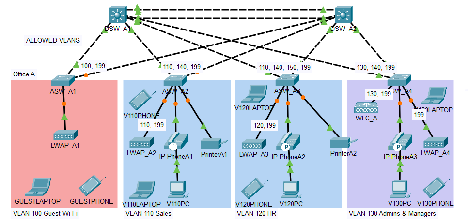
In addition, just as shown in the diagram above, the trunk connection between switches will allow only the VLANs available at the specific Access switch, rather than allowing all VLANs. This keeps each VLAN’s broadcasts off the links that don’t need them, since there is no reason for a switch to forward traffic for a VLAN that isn’t present on it.
Trunks are also used for the ports that connect to access points. The APs use local switching meaning that each individual AP tags the traffic of the clients connected wirelessly to it and sends this traffic to its respective Access Switch. As such, the AP port will include traffic for VLAN for this department plus the Management VLAN, where the Management VLAN will be the native VLAN in this connection since the AP sends its own traffic untagged. Reasons for using local switching will be explained in the Wireless part.
The link between WLC_A and ASW_A4 is also a trunk, but this trunk includes only VLAN 199 (Management). Client traffic does not go through the controller, thus the controller only has to communicate with its access points. This connection remains a trunk in order to be able to implement central switching in the future without any need to change the port type. The native VLAN for this link has been set to VLAN 199 (Management) as opposed to VLAN 938 (which is not being used anywhere) in order for the traffic of the controller to be directed to VLAN 199 properly.
Here is an example of port assignments used on Office A’s Access switches. You can find all of the port assignments for every device in the topology at the link:
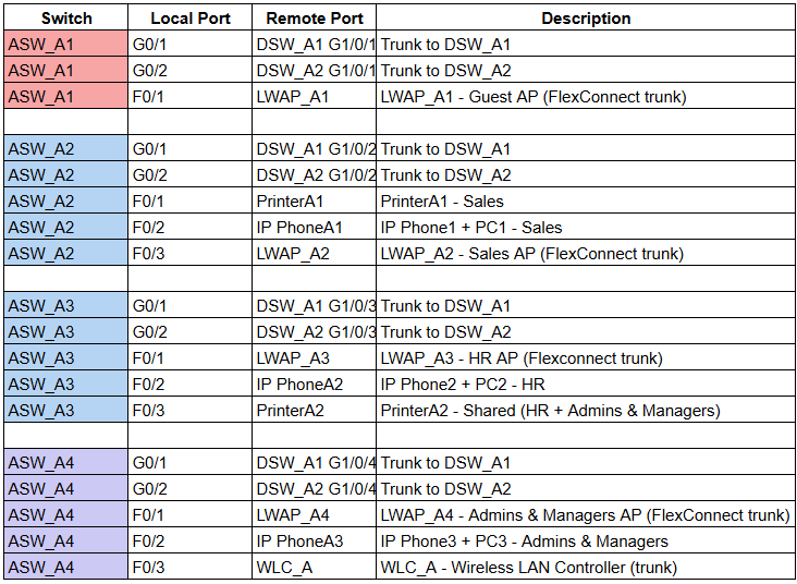
After configuring the VLANs and trunk links, the remaining ports on Access switches (including the Internal Servers and DMZ switches) were configured as access ports for their assigned VLANs, and all unused ports were administratively disabled. VLANs are also configured on the Distribution switches for inter-VLAN routing.
L2 EtherChannels
Both pairs of Distribution switches in Office A and B are connected with two redundant links. I configured EtherChannels using the name Port-channel1. In Office A, an open industry standard, LACP (Link Aggregation Control Protocol) is used. In Office B, a Cisco proprietary protocol PAgP (Port Aggregation Protocol) is used. I am aware that using different protocols for the same type of devices is not recommended. This is only for lab purposes.
Each pair of Distribution switches actively tries to form an EtherChannel, meaning LACP in Office A uses active mode on both switches, while PAgP in Office B uses the desirable mode on both switches.
EtherChannels are also configured as trunk links. Unlike the Access-Distribution trunks, I allowed all VLANs here since both Distribution switches must be able to carry traffic for any VLAN in the offices, especially during failover scenarios. DTP is explicitly disabled and all unused ports on Distribution switches are administratively disabled.
Part 3 - IP Addresses, HSRP and L3 EtherChannels
IP Addresses
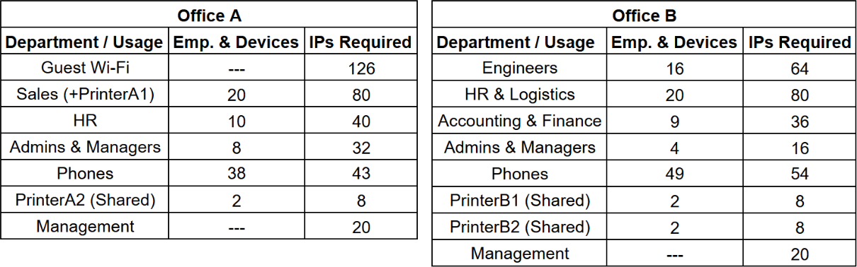
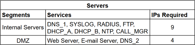
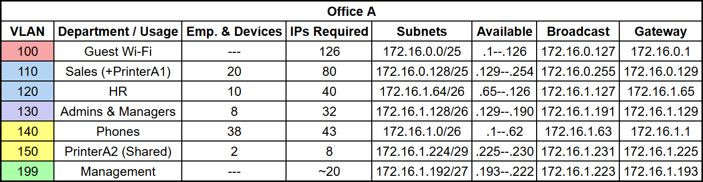
You can see the number of employees and devices in the company below. The “IPs Required” column doesn’t match the number of employees or devices. I applied a growth factor of x4 to each department, but not to every row. Phones stay close to the employee count, since each employee just gets one desk phone. Guest Wi-Fi is an assumption for visitors and Management is sized from the number of network devices.
I used the private IP address block 172.16.0.0/12, as defined in RFC 1918. Before explaining IP addressing, I would like to include a quick refresher on the subnetting from my notes, since the same reasoning applied across the whole network.
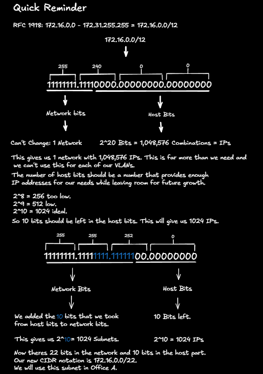
The subnet 172.16.0.0/22 is assigned to Office A. To find the subnet for Office B, I learned the range of the subnets by looking at the octet that is not all ones or zeros in the network mask. In this case, it’s the 3rd octet. Then I subtracted the network mask’s 3rd octet from 256. This gives the “Magic Number”. You can also just take the value of the last network bit in that octet.
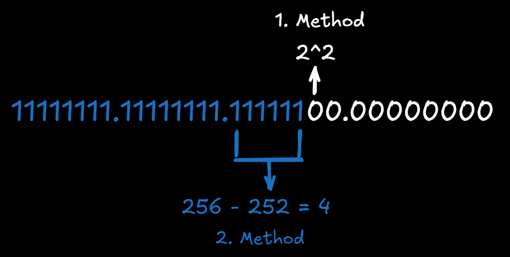
The Magic Number is 4 and tells us how much the subnets increase by in that octet. This means 172.16.0.0/12 is divided into 1024 subnets with a /22 mask, each providing 1024 IPs, and their range increases by 4. Two of these subnets are assigned to the offices.
Office A = 172.16.0.0/22
Office B = 172.16.4.0/22
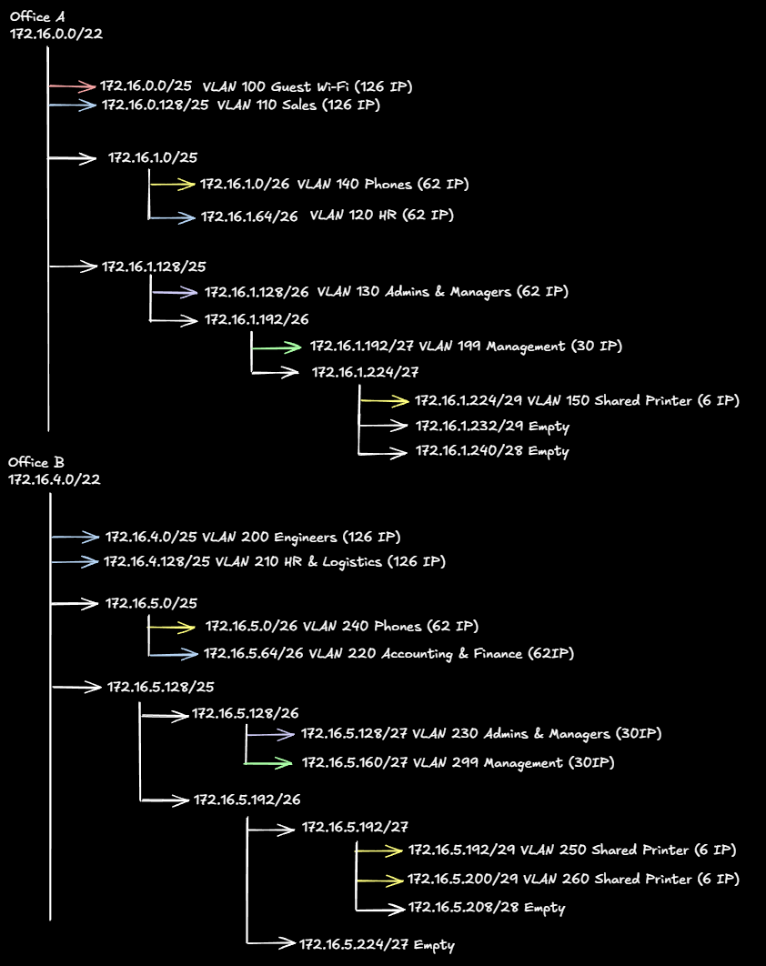
After subtracting 2 IPs for the Network and Broadcast IDs, each of these subnets gives 1022 Host IPs for both offices. Still far more than needed, which is why each office’s /22 block is divided further using VLSM (Variable Length Subnet Masking) based on actual need instead of one fixed mask.
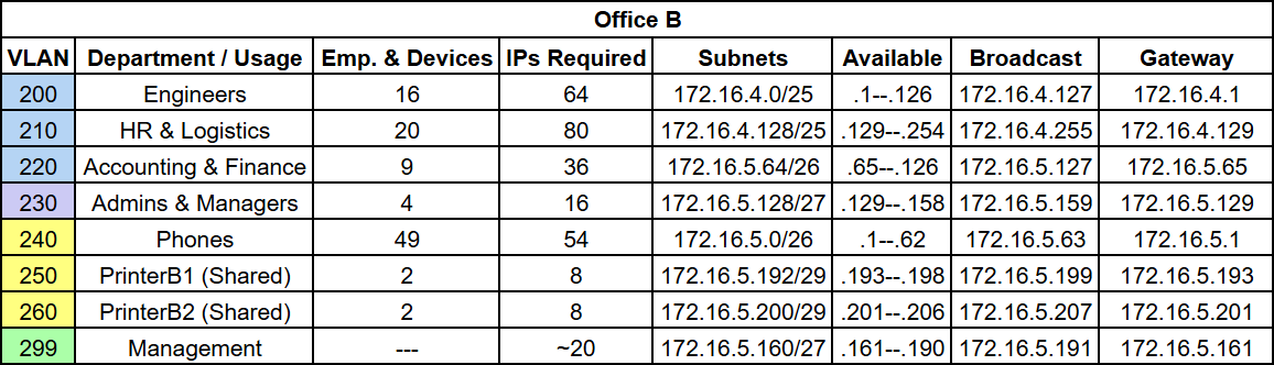
To keep this writing from becoming unnecessarily long, here is the full subnet breakdown for both offices.
You can also see the full table, including servers:

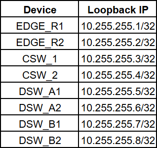
For Point-to-Point connections, I used a different subnet, 10.255.254.0/24, to keep them easy to read and clearly distinguish from the VLAN address space. For loopback addresses, I used another dedicated subnet, 10.255.255.0/24. The third octet, .254 means Point-to-Point link and .255 means loopback. This makes it easier to recognize. The links to the two ISPs are the exception because their addresses come from the providers, 198.51.100.0/30 from ISP_1 and 192.0.2.0/30 from ISP_2.
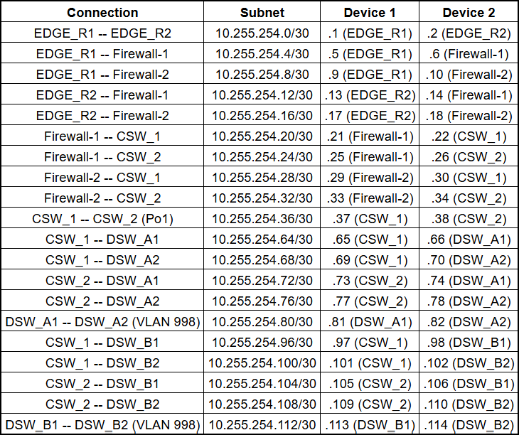
I originally planned P2P links as /31 subnets. However, Packet Tracer does not support /31 masks. This is why I used /30 subnets for P2P links.
As you can see from the table above and the topology, there is no link between Firewall-1 and Firewall-2 because Cisco ASA in Packet Tracer does not have the failover feature. For this reason, only Firewall-1 was configured to be an active gateway for the DMZ, while the DMZ interfaces on Firewall-2 were administratively shutdown. Firewall-2 is still used as a backup link for its inside and outside interfaces.
Now you may question why I chose to use two firewalls although they can never work in failover mode. The reason behind this is that during my research of network designs online, I found out that in some 3-tier architectures there was just one firewall which all devices were passing through. At the very beginning, it seemed to be a bad design because if that firewall fails, entire network is shut down. However, this is not a design flaw. Packet Tracer does not support dual firewall failover. Still, for people who don’t know about this limitation in Cisco Packet Tracer, it looks like a bad design. This is why I used two firewalls anyway to show a real enterprise network design.
Loopbacks are only assigned to Layer 3 devices. The firewalls are excluded because Cisco ASA does not support loopback interfaces. The Access switches are also excluded because they operate at Layer 2 and don’t run any routing protocol. Their management is handled through an SVI in the Management VLAN instead, which is also configured in this part.
HSRP
After configuring IP addresses on each device, Cisco proprietary protocol HSRP (Hot Standby Router Protocol) was configured on the Distribution switches. As you might know, HSRP gives each VLAN a single shared virtual gateway IP. End devices are only aware of this one gateway IP. If the switch currently forwarding for a VLAN fails, the other takes over automatically, without making a change on the client side.
HSRP version 2 was used instead of version 1, because of the larger group number range and the dedicated multicast address (224.0.0.102).
HSRP priority was balanced across VLANs so both switches carry real traffic under normal conditions instead of one waiting idle as a pure backup.
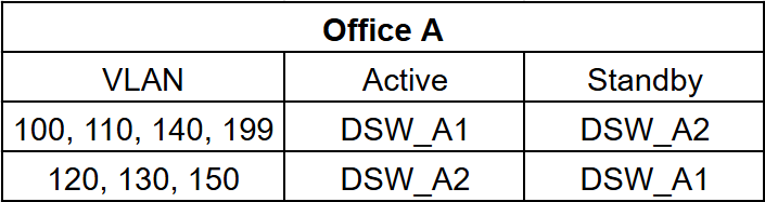
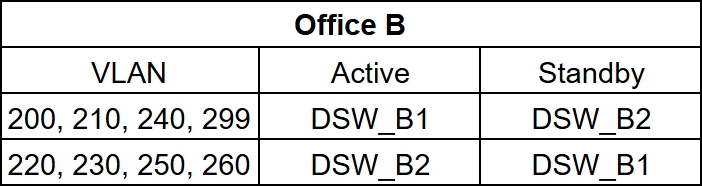
Priority was 110 for Active and 90 for Standby across every VLAN and preempt was enabled everywhere. The same logic was also applied on the Core switches, for VLAN 300 (Internal Servers). CSW_1 was set as Active (priority 110) and CSW_2 as Standby (priority 90).
L3 EtherChannel
EtherChannel between CSW_1 and CSW_2 was configured as Layer 3 Etherchannel because unlike Distribution switches, the Core switches do not carry any VLANs so there is no trunk, no native and no HSRP involved here. The ports were converted to routed ports and a single IP address was assigned directly to the logical Port-channel1 interface. This is the same way you would address any other routed point-to-point link. Instead, redundancy for this connection is handled by OSPF, which I will cover in a later part.
PAgP, a Cisco proprietary protocol was used for this L3 EtherChannel. Both switches actively try to form the channel using the desirable mode.
Part 4 - Rapid Per-VLAN Spanning Tree Plus
You might be wondering why I configured Rapid PVST+ after the IP addressing part and not Part 2. This is because the placement of the Root Bridge in this network design depends on the HSRP Active switch of a particular VLAN. Therefore, I had to decide this in the HSRP part and then configure Rapid PVST+.
If HSRP and Rapid PVST+ are misconfigured, traffic will not be routed via the optimal path. For instance, if HSRP Active for a specific VLAN is DSW_A1 and the Root Bridge is DSW_A2, all traffic must go through DSW_A2 because it is the Root Bridge. This is an extra hop that is not necessary and results in latency and extra load on the link.
VLANs 100, 110, 140, and 199 would be Active on DSW_A1 according to the HSRP priorities I configured before. VLANs 120, 130, and 150 would be Active on DSW_A2. In order to keep Layer 2 and Layer 3 in sync, I configured DSW_A1 as Root Bridge for its own VLAN group and Secondary Root for the other VLAN group. DSW_A2 was configured the other way round. On Access switches, I only changed their STP mode to Rapid PVST+. The priority of leaf switches remained unchanged since they were not supposed to become root.
PortFast and BPDU Guard have been configured for all end-host and server ports. In Rapid PVST+, the port takes a few seconds before it reaches the forwarding state. PortFast bypasses the entire process; hence, the port goes into the forwarding state straight away because there is no possibility of any loop formed by the end-hosts and servers. The configuration of BPDU Guard was done because in case any BPDU is detected on the ports, then the port will be shut down instantly.
Configuration of DMZ_SW1 was the same even though Firewall-2’s DMZ interfaces are shut down. DMZ_SW1 is the only switch in the DMZ. Because of this, there is no loop to manage. However, I still configured Rapid PVST+ mode, PortFast, and BPDU Guard on DMZ_SW1’s server-facing ports for consistency.
WLC_A, WLC_B and the access points are an exception since they connect over trunk ports. I used the command spanning-tree portfast trunk rather than the usual command, since the usual one has no effect on trunk ports. PortFast and BPDU Guard were not enabled on inter-switch connections like DSW-to-ASW trunk links, CSW uplinks, and EtherChannel members, as these connections could actually create loop formations. This way the proper operation of Rapid PVST+ can be maintained.
Both Layer 2 and Layer 3 redundancy are now synchronized, ensuring that all VLAN traffic travels through the most efficient path. Additionally, PortFast and BPDU Guard for end-host ports improved user connectivity speed while providing security against unauthorized switches being plugged in.
Part 5 - OSPF
This part got a bit long because I encountered a Packet Tracer limitation while setting up OSPF. The configuration includes a workaround and because of it, I would rather explain the whole configuration than leave something in the files that makes no sense.
I used multi-area instead of a single Area 0. Area 0 covers the Firewall links, the Core switches, the EtherChannel between them and VLAN 300. Area 10 is Office A, Area 20 is Office B, so the Core switches end up as ABRs. In production a network this size would just use one area. I picked multi-area on purpose, and built it this way to show how it would work at scale.
Router IDs are statically assigned using loopbacks. Otherwise, the router would select its own automatically, but then this ID could be different when the router reboots again and that causes problems. The command auto-cost reference-bandwidth 10000 is enabled in all routers in order to make OSPF able to distinguish the speeds of links. All users SVI, VLAN 300, all loopbacks and the firewall interfaces of core switches are passive. MD5 authentication with the password OSPFKEY123 is enabled in all three areas and the /30 links have ip ospf network point-to-point configuration since there is no need to elect the DR/BDR on this link.
Route Summarization
As a reminder from the IP addressing part, each office has a /22 block, and every VLAN in it fits inside the first half of that block. That means Office A can be summarized as 172.16.0.0/23 and Office B as 172.16.4.0/23. This is a design choice because it allows summarization. Therefore, the rest of Area 0 will not have to know every VLAN subnet in each office. It will be enough for Area 0 to have one route for each office. The ABR devices, in this case, the Core switches, will have information about all routes, while everything else will not.
However, you cannot actually see the advantage in this network since I do not use OSPF in the firewalls. This is also a design choice. A firewall is a policy boundary, and if it ran OSPF, the inside and the outside would share the same routing information. This is not what I wanted. So static routes carry traffic through the firewalls in both directions instead. As a result, Area 0 has no device other than the Core switches that could use the summaries. The Core switches create the summaries, but none of the devices use them.
Still, for a network that has many more Cores and Distribution switches than the one that I have designed, this is where the benefits start to pay off. Instead of having all the exact routes in every office, each Core will just have a few summaries. This is the reason why I built it this way, to show again how it would work at scale.
The plan was for this to work with the per-VLAN cost design. Summarization helps to keep the routing tables smaller at the area boundaries. The cost values of the SVIs define which Distribution switch would serve each VLAN. This solution makes all VLANs connect to one switch each with a routing table minimized. The summarization procedure works just as I planned it. The problem with the cost-based strategy is caused by Packet Tracer.
In Part 4 I split the VLANs across the two Distribution switches, which sorts out traffic leaving the office. However, if the router sends a packet inside the VLAN it sees two paths and does not know which of the switches is Active. If it chooses the Standby switch the packet will arrive at the switch where the port of that VLAN is blocked by the STP protocol and the packet will go through the EtherChannel to the Active switch and then to the Access switch. It is an additional hop on every packet coming back and the traffic follows different paths in both directions.
To fix this I configured the OSPF costs on the SVIs so each switch advertises its own VLANs at 10 and the other VLANs at 1000. Now a VLAN costs 20 through its Active switch and 1010 through the other switch. If the Active switch fails its LSA disappears completely so redundancy is not affected. On real IOS that is the full solution. In Packet Tracer it did not work.
The Core pushed all intra-area traffic through one Distribution switch regardless of cost. For the VLANs that switch owned this was correct. Everything else went through that same switch too at 1010 even though the other switch advertised the same prefix at 20.
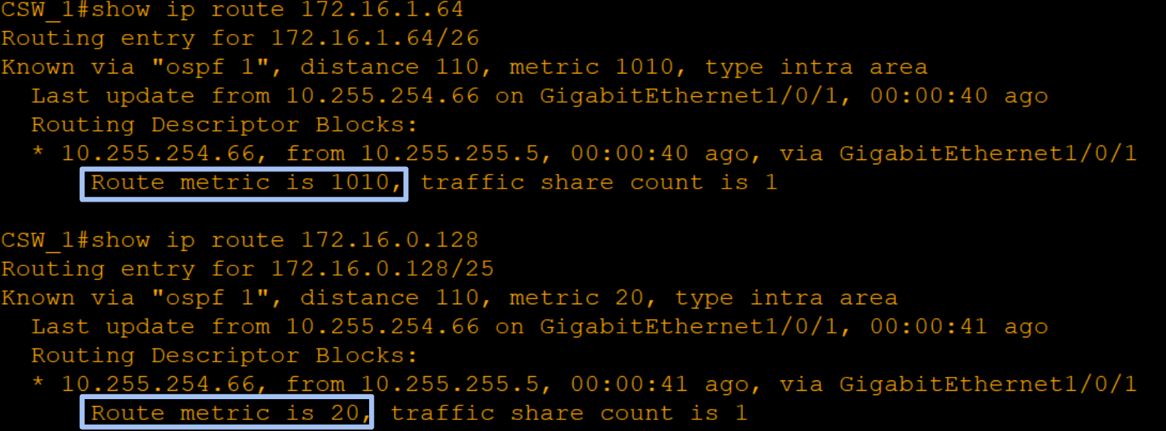
Before blaming the simulator I went to the database because that’s where a config mistake would show up:
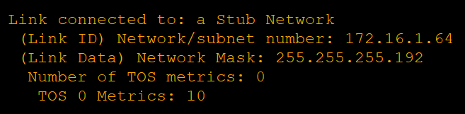
Everything was where it should be. The LSAs were right, both adjacencies were FULL, the Core had all the information it needed. The inputs to SPF were correct but the outputs were wrong.
I tried using the command clear ip ospf process and it did nothing. Switching to broadcast dropped the adjacencies and also fixed nothing. I widened the gap all the way to 1 against 65000. This changed which switch got picked globally, but several prefixes still went the wrong way. To be completely sure, I rebuilt the entire test in Office B on a different pair of switches, and the result was exactly the same.
After that I looked it up and Cisco’s own documentation says Packet Tracer simulates IOS rather than emulating it. Other people have run into the same kind of thing in multi-area setups too. SPF doesn’t seem to evaluate stub links per prefix the way real OSPF does.
The workaround
The cost was right, but the simulator didn’t use the values. Therefore, I manually configured the paths using static routes for each of the Cores, one per VLAN.
Since distance 1 is better than OSPF’s 110, these paths override OSPF while both switches are alive, however, failover remains OSPF’s responsibility. If a Distribution switch dies, the path is lost, static route becomes unreachable due to non-existing next-hop, and OSPF uses its route via another switch. After the Distribution switch restarts, the static route is also restored. Therefore, the redundancy configuration remains unchanged. All that happened was switching from one of the working paths to another.
The default route configured by each Distribution switch learned from the Core also had the same issue. The packets from each flow went out using different Cores, thus each Distribution switch had to have the static default routing to their preferred Core.
I have kept both SVI and the cost values even if Packet Tracer does not use them, since that is how things would work on the real hardware. The costs represent the actual configuration while the static routes only ensure that simulation behaves the way it should according to the cost values.
VLAN 998
This is the point I was referring to in VLANs section. As all the user VLANs are passive, the two Distribution switches in the office cannot form an adjacency with one another. The EtherChannel formed between the two Distribution switches is a Layer 2 link with no IP configuration at all. It works perfectly fine until both uplinks of that switch fail. The EtherChannel link remains up, but this switch becomes an island for OSPF as it has no neighbors and hence, loses its default route.
The VLAN 998 is a VLAN configured over the same EtherChannel link along with an SVI on both ends, which makes it possible to form an adjacency. This VLAN exists in the office’s own area as both the ends are in the office and ip ospf cost 100 makes sure that the VLAN is used only when necessary. This VLAN also covers the hosts. Without any interface tracking in Packet Tracer, the isolated switch stays alive in HSRP, but now it can send the hosts’ traffic to its peer via VLAN 998.
Part 6 - Network Services
DHCP
DHCP_A and DHCP_B serve as the DHCP servers for Office A and Office B, each handling its own office’s VLANs. PCs, laptops, phones and the access points use DHCP. Printers and the WLCs keep static addresses. Both DHCP servers were also given a static IP themselves, in VLAN 300, with 172.16.8.1 as their default gateway.
The first ten usable addresses of every pool are excluded from the lease range, so they’re never assigned to clients. This is done by simply starting each pool’s range ten addresses past the gateway, rather than using a separate exclusion command, since Packet Tracer’s DHCP server doesn’t have an exclusion field of its own. DHCP configurations look like this:
DHCP_A:
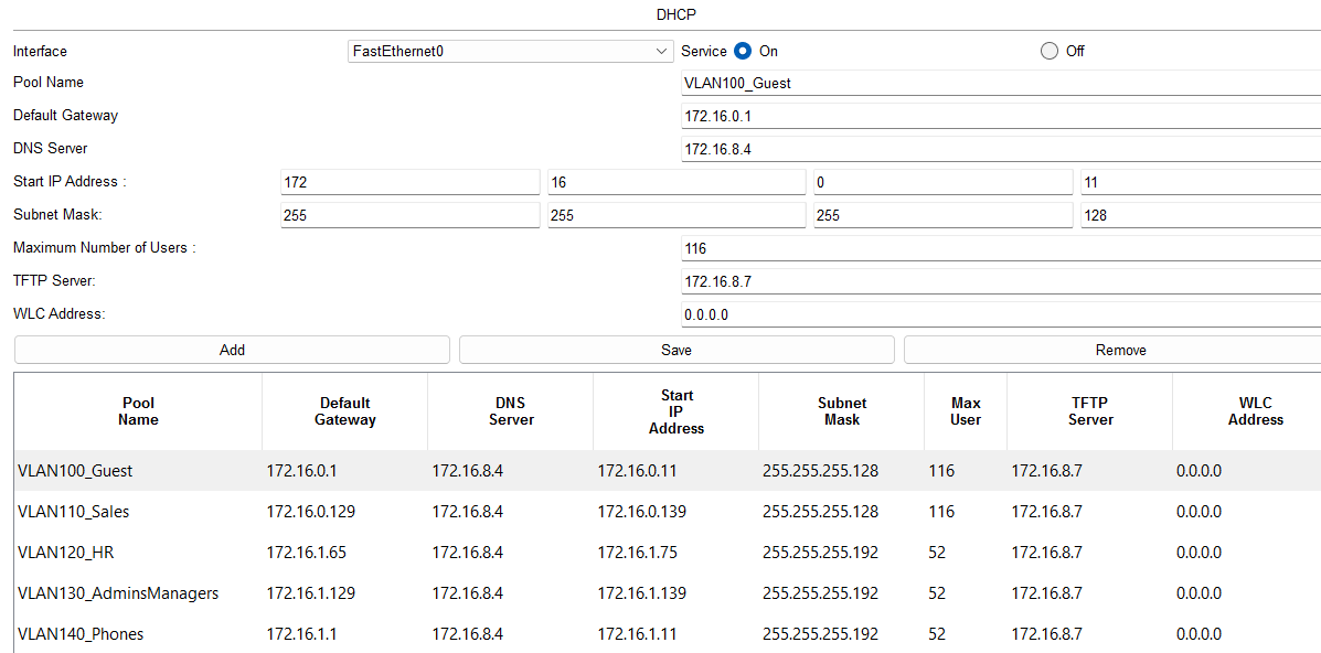
DHCP_B:
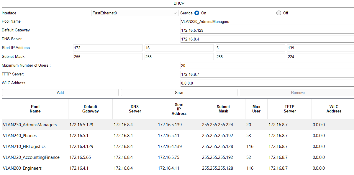
DNS server is set to DNS_1 (172.16.8.4) on every pool. TFTP server is set to 172.16.8.7, which is the same server used for FTP, more on that in a later section. The voice pools are the exception and point to the call manager instead, as explained in the IP Phones section. The WLC Address field is only filled on the two Management VLAN pools. Packet Tracer’s lightweight APs can’t take a static address, so they lease one from the Management VLAN pool and learn their controller’s address from this field.
The Distribution switches relay client requests to the servers using ip helper-address, since DHCP requests are broadcasts and don’t cross VLAN boundaries on their own. Each office’s Distribution switches point to their own DHCP server only, DSW_A1 and DSW_A2 to DHCP_A, DSW_B1 and DSW_B2 to DHCP_B. The Core switches don’t need this, since the DHCP servers already sit in the same VLAN as the Core switches’ own SVI.
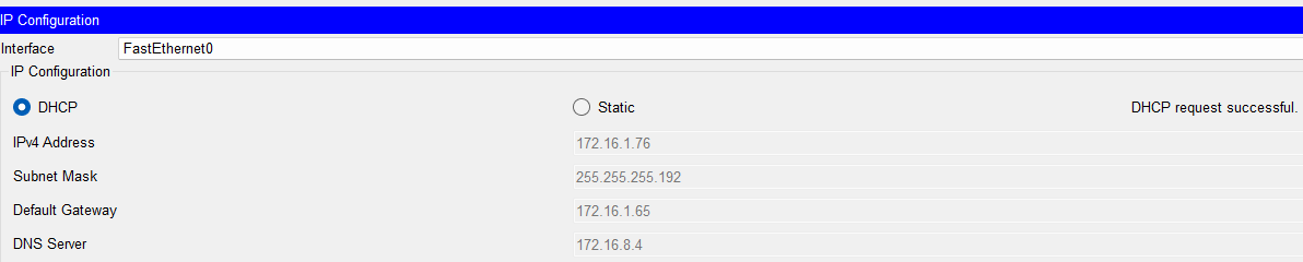
After completing the configuration, I tested DHCP on PC2 (HR) and it worked correctly:
DNS
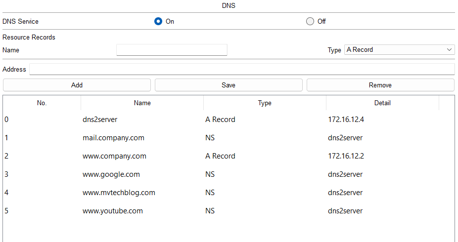
DHCP assigns 172.16.8.4 as the DNS server on every pool so DNS_1 is the DNS server the entire network uses. It resolves www.company.com, the company’s own website in the DMZ, as a plain A record, while google, youtube and mvtechblog are all delegated.
This shows how DNS delegation works in a real enterprise network, where internal and external name resolution are handled by separate servers instead of one server holding every record. The delegation is set up on DNS_1 with an NS record for each domain pointing at dns2server, plus an A record for dns2server itself:
DNS_2 holds the actual record for that domain:
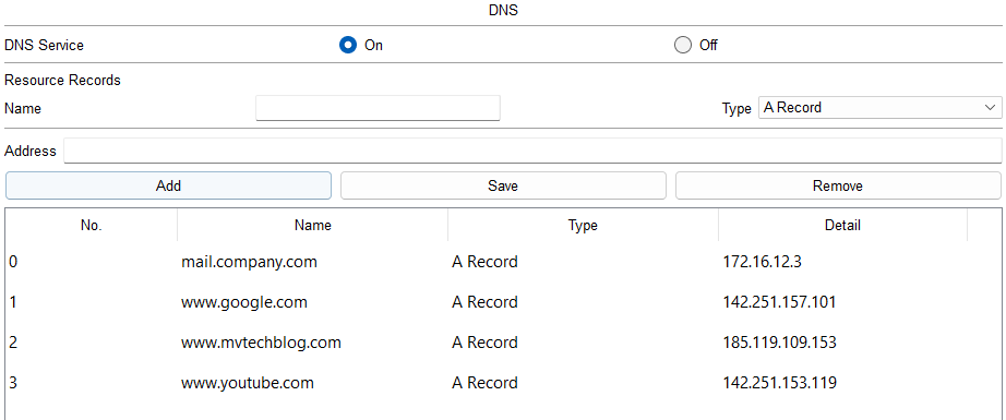
The PC only ever queries DNS_1. DNS_1 is the one that resolves the delegated name through DNS_2 and hands the result back. The client never talks to DNS_2 directly. The DMZ Web Server hosts a simple company page at www.company.com, which confirms that DNS, routing and the DMZ work together end to end.
Here is a test I ran with a simple copy of my own website.
Keep in mind that if you’re opening this Packet Tracer file for the first time and loading a website for the first time, it can take quite a while to load. You can speed this up with the Fast Forward Time button in the bottom left corner of Packet Tracer.
NTP
The NTP server is placed in VLAN 300 at 172.16.8.9. All routers, switches, and firewalls refer to it as clients, and thus the entire network operates using one clock.
NTP authentication is used with a shared key, meaning that the device only gets synchronized with the server which knows the key. Otherwise, anyone would be able to provide the time to any device on the network unnoticed.
I checked the configuration of all IOS devices. Here is an example configuration for DSW_A1:

DMZ_SW1 and Edge Routers are an exception because their NTP request goes through the firewall into the inside zone which is blocked by the default ASA configuration and thus remain unsynchronized until the ACL part where I open the access rule for them. Firewalls are configured in the same way, but without the timezone line since Packet Tracer ASA doesn’t have clock timezone.
Remember that NTP synchronization takes a lot of time. You won’t see the synchronization on opening the Packet Tracer file.
SYSLOG
The syslog server sits next to NTP in VLAN 300, at 172.16.8.5. Every router and switch sends its log messages there:
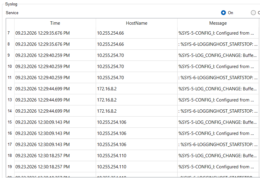
The firewalls are the exception. Packet Tracer’s ASA has no logging commands at all, so they keep their messages locally and send nothing.
DMZ_SW1 and the Edge Routers are in the same position as they are with NTP. Their messages would have to cross the firewall into the inside zone, so they stay silent until the ACL part.
SNMP
The community string of every router and switch in the network configuration is read-only. The GET request is successful while the SET request fails. The monitoring tool can obtain interface counters, uptime, and other information about the monitored device but cannot do anything to the device itself. This is a reasonable option for the monitoring tool since it needs read-only access.
There is no SNMP manager in my network. As the Packet Tracer server does not have the SNMP service, the manager is represented by the PC. The PC has a MIB Browser on its Desktop.
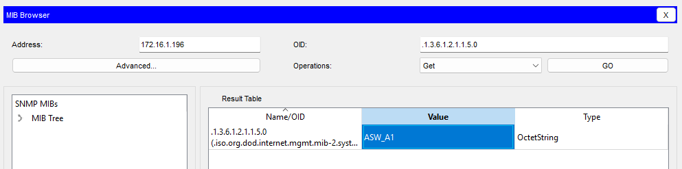
SNMPv3 would be the right choice here because v2c sends the community string in clear text with no authentication or encryption, so anyone capturing a packet has read access to every device. Packet Tracer allows configuring only snmp-server community for these switches, and does not provide v3 or trap features, hence uses v2c.
Again, the firewalls are left out, since snmp-server is not available in Packet Tracer’s ASA command set.
LLDP
Cisco devices use CDP out of the box and that is okay as long as the entire network is Cisco. LLDP is the IEEE standards based version of CDP and therefore works when the network is not entirely Cisco. I disabled CDP and configured LLDP on all devices. The access ports with an IP phone on them are the one exception. Packet Tracer’s phones learn their voice VLAN from CDP and nothing else, so CDP stays enabled on those ports only.
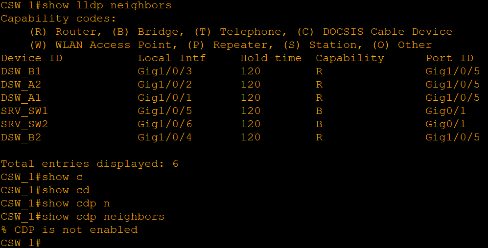
Neither protocol works safely alone. Both reveal the device model, software version, and port number in plain text without any authentication, so every device hearing those packets gets an inventory of whatever it’s connected to. LLDP being a standard doesn’t change that, it only means more vendors speak it.
The information is useful between the infrastructure devices, but not between the infrastructure and the end devices. Therefore, on the access switches, I disabled the transmit capability for all the ports connected directly to end devices. The ports remain in the receive mode so the switch learns what it’s connected to but doesn’t disclose itself to the user side.
Firewalls don’t take part in the process. In the ASA of Packet Tracer, there is no CDP or LLDP command set available.
RADIUS
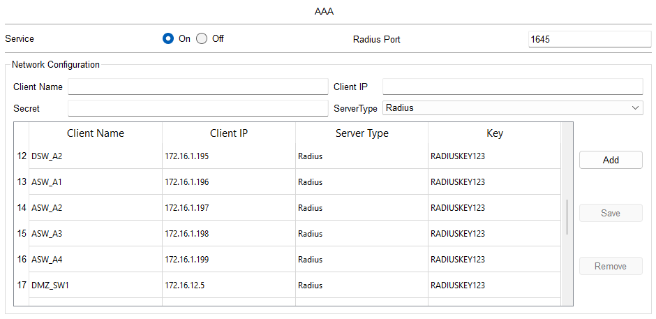
Each device until now had its own user account in the local storage. This is fine until you need to make changes like adding a new person or changing passwords, and then you need to edit twenty devices individually. The RADIUS moves the users to the central server and requests the devices to communicate with it. The central server is in VLAN 300 at 172.16.8.6. The devices have their IP addresses, shared secret and all user accounts stored in the central server instead of each individual device. The login list in each device asks the permission of the server first and uses the local user account only when it cannot reach the server. Otherwise, a problem with the server would result in locking out all devices simultaneously.
However, this backup plan is not a security weakness because it only applies to the server being unavailable, not for the server providing a rejected response to the authentication request. If RADIUS provides a rejected response, the device considers it as such and rejects the login attempt. The local account acts as the backup account here.
One note on the port number. 1645 is the old Cisco default, while the standard ports are 1812 and 1813. Packet Tracer’s server listens on 1645, so that is what the clients use.
SSH
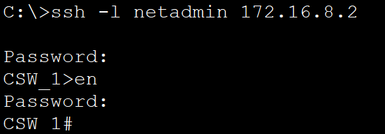
Telnet sends everything in clear text, including the password, so it shouldn’t be used on the management interface. Each device has SSH configured.
An RSA key cannot be generated without a domain name, because the key is named after the device and the domain. 2048 is the maximum size of the modulus Packet Tracer accepts. Version 1 is disabled because of its known weaknesses.
Restricting the VTY lines to SSH transport is what actually closes the door. Otherwise, Telnet would still be possible despite configuring SSH at the same time. Also VTY lines use the RADIUS list of logins configured previously, discard connections that are idle for 15 minutes, and disable interrupting log messages while entering something.
There are three exceptions to the rule above: SRV_SW1, SRV_SW2 and DMZ_SW1 don’t accept login authentication default on their VTY lines. They still use the RADIUS login list, because with AAA enabled the default list applies automatically.
The firewalls have another approach. ASA firewall restricts access to SSH by source address and interface rather than by means of a VTY access-list, meaning that it states which network addresses and interfaces are allowed access. There is no ssh version command in Packet Tracer’s ASA, therefore, it will remain at default.
At this point, the VTY lines accept connections from any source within the network. This is narrowed down to the admin VLANs later, in the ACL section.
NAT
The Internet Router had some static routes to the private address space, which will not exist in any case on the real internet. They were just added to provide connectivity when building the internal network. NAT will solve this problem.
NAT typically operates on the firewall, but in this network, the Edge Routers are the final point in the network before the service provider’s side. Everything behind them is private. So if NAT operates at the firewall level, it would transform the private addresses into another set of private addresses because the outside interfaces of the firewall, which connects to Edge routers, are also private. Therefore, it makes sense to operate NAT at the Edge Routers level.
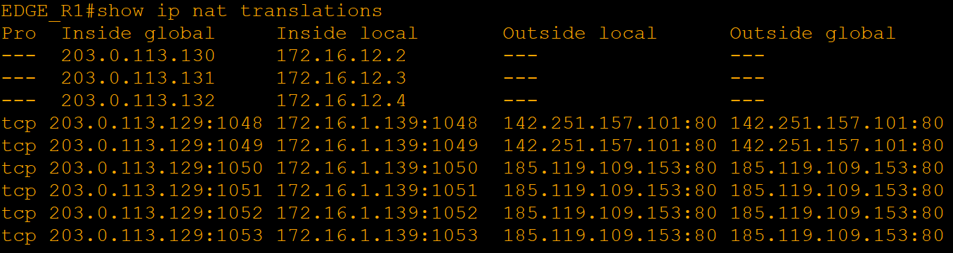
The company has an IP block 203.0.113.0/24 and announces it to both providers. This is the smallest IP range which the Internet accepts. As it is owned by the company (and not a provider), the IP address for the traffic won’t change depending on the provider through which traffic leaves. Otherwise the identity of the company will be changing on every failover, breaking all allowlisting which may depend on IP addresses. All traffic will be translated with PAT to this IP address range. DMZ servers get static one-to-one NAT instead, because DNS points at them and their addresses cannot change.
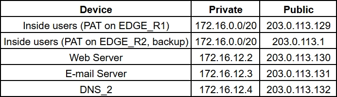
Both Edge Routers carry the same DMZ translations, so the servers stay reachable when one of them is gone.
Multihoming and BGP
Each Edge Router peers with its own provider over eBGP, and both advertise the company’s block. On the outgoing path, the entire network will use EDGE_R1. The firewall default gateway routes will use EDGE_R1, with EDGE_R2 being secondary but with a higher administrative distance value. In case of a failure in EDGE_R1, the link will fail, and the firewall will switch over to EDGE_R2 automatically.
If the link to ISP_1 goes down, EDGE_R1 loses its default route, and a floating static route forwards the traffic to EDGE_R2. This will actually be iBGP in production; however, this feature is not supported in Packet Tracer.
The inbound traffic, on the other hand, is what the BGP does best. In case of failure of the session by the provider, the provider will stop advertising the subnet, and therefore the internet will access the network through the other provider. Static routing cannot accomplish this.
Traffic returning has to be directed at the router where the NAT is done because there is no sharing of the state information between the two routers. Usually, you extend the alternate path through AS-path prepending, however, Packet Tracer’s BGP does not have route-map, weight or default-originate. Thus, EDGE_R1 advertises 203.0.113.128/25 and EDGE_R2 advertises the covering /24. The more specific route wins, therefore, addresses advertised by R1 are going through R1 when it is active and fail over to the /24 when it is not.
The firewall does not influence the process of choosing the best route. Packet Tracer’s ASA does not support SLA monitoring to check the provider, and no interface tracking is available as well, thus two standard ways of automatic failover of the gateway are out of use. Also, there is a peculiar behavior of the ARP table: ASA resolves destination IP address rather than the next hop IP and uses the router’s proxy ARP; thus, once failover occurs, ASA still has the MAC of the previous router and must clear the table.
The two providers’ routers have been connected, with an Internet core behind them. The network stops at the edge routers, so this side exists just to give the peering some place to be terminated.
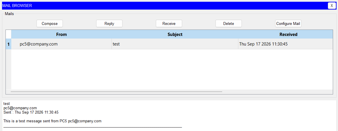
The mail server is placed within the DMZ at IP address 172.16.12.3, which appears as 203.0.113.131 to the internet. It serves the domain name company.com using SMTP protocol for sending and POP3 protocol for incoming mail, and the accounts of users are located on the server.
To connect to it, clients use the name. The name mail.company.com is delegated from DNS_1 to DNS_2 as any other external domain name is delegated, and DNS_2 stores the name. In the real-life scenario, the entire company.com zone should be delegated only once, and all the names below it would be delegated automatically. In Packet Tracer, each name is delegated individually since DNS server matches names exactly.
I tested it between PC1 in Office A and PC5 in Office B. The ACLs block any direct connection between the two offices, but both can reach the DMZ, so they still exchange mail through the shared server. That is the intended shape. The offices are kept apart, and common services sit in between.
From the internet, only SMTP and POP3 are opened to the mail server on the firewall. Both protocols send credentials and content in clear text here. In production they would run over TLS, which Packet Tracer’s mail server does not support.
FTP
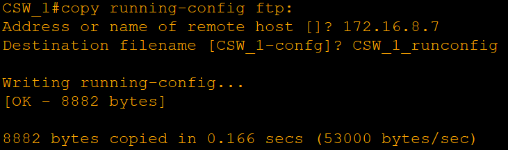
172.16.8.7 is an FTP and TFTP server. The TFTP is provided to clients via DHCP service. FTP is used to send any critical data due to the authentication process which is performed while TFTP does not require one. In our case FTP is used for backup purposes. The configurations and IOS images are loaded from devices to the server and vice versa. There is a username and password which are provided for the server for each of the devices separately since the copy command does not prompt for them.
The configuration of the firewall was also required for this task. The Edge Routers and DMZ_SW1 devices do not belong to the inside zone and therefore FTP access to them had to be enabled the same way as NTP, syslog and RADIUS services.
IP Phones
Each office has IP phones sharing the access ports with the PCs behind them. The phone tags its own traffic with the voice VLAN and passes the PC’s frames untagged, so one cable carries both. Office A uses VLAN 140 and Office B VLAN 240, which keeps voice in its own subnet and makes it easy to prioritize later. This is also where the two exceptions in the LLDP and port security sections come from.
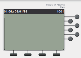
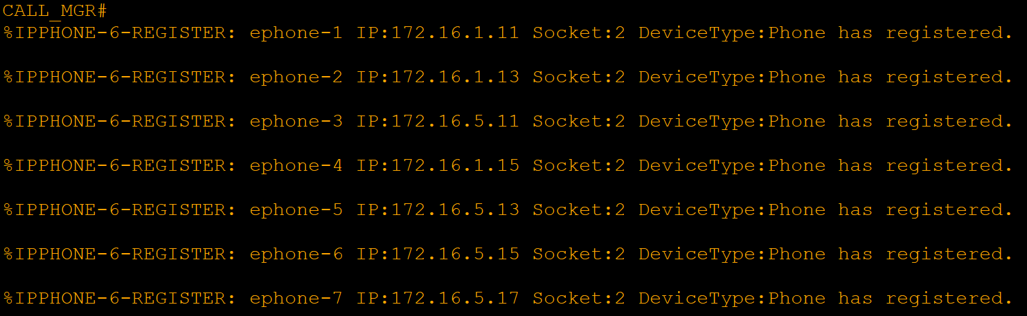
For the call agent I added a 2811 router, CALL_MGR, at 172.16.8.11 in the server VLAN, running Cisco Unified CME. The phones find it through DHCP option 150, which is the TFTP Server field in the Packet Tracer DHCP pools, set on both DHCP_A and DHCP_B for the voice pools. Extensions 1001 to 1007 are assigned automatically as phones register.
Calls work in both directions between the two offices, which also proves the routing between the sites is fine for more than ping.
CME is a small branch product and it is not what a new deployment would use today. I used it because it is the only call agent available in Packet Tracer. What it stands in for has changed, but the network side has not: voice VLAN, PoE, provisioning through DHCP and QoS marking are all still exactly this. A company of this size today would run Microsoft Teams Phone, Zoom Phone or Webex Calling, reach the PSTN over a SIP trunk instead of a PRI, and use SIP handsets or softphones, where the voice VLAN is learned through LLDP-MED rather than CDP.
Part 7 - ACLs and Layer 2 Security
Access Control Lists
Distribution Switches filter traffic between VLANs as well as between the two offices. Firewalls handle traffic between the inside, DMZ, and the Internet. The rules follow the trust zones from Part 2. Each zone can only reach what its role needs.
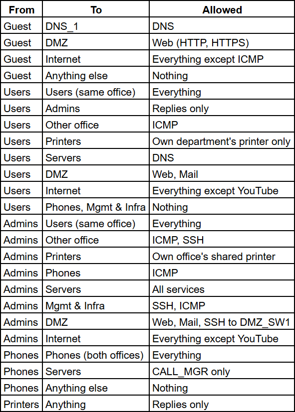 Only Admins and Managers VLANs have access for management. Both offices’ devices can be accessed through from Managers VLANs, including Edge Routers and firewalls. No other VLANs can initiate any management connection at all.
PrinterA2 is available only for HR and Admins, PrinterB1 for Engineers and HR & Logistics, PrinterB2 for Accounting & Finance and Admins. This is enforced on the printer VLAN’s own SVI, so the user VLANs can share a single access list. There’s no need to mention DHCP in the table because each of the user access lists permits it first, so clients can always get an address.
The ACLs are stateless, so “replies only” means the return traffic of a connection that someone else started such as a user answering an admin’s ping. These are also extended access lists, so they are applied inbound on the SVIs, right at the source of the traffic. The printer VLANs are the exception, where the list that decides who can reach the printer is applied outbound, towards the printer. They must be applied on all four Distribution switches as opposed to one per pair because HSRP allows either one of the two switches to become the gateway.
On the firewalls, the policy between the Internet, the DMZ and the inside is shown below.

As you can see above, the DMZ servers can only reach the Internet for what they actually need: DNS, sending mail, and updates over HTTP and HTTPS. The DMZ is untrusted in both directions, which is the whole point of having one. The Edge Routers sit outside the firewall, so the same management services had to be opened for them as well. Until this point they could not reach the NTP, syslog or RADIUS servers at all, which is what the RADIUS section referred to. Return traffic for connections started from the inside is allowed by the firewall’s stateful inspection, so “Nothing” in the table only covers connections started from outside.
Packet Tracer’s ASA does not recognize several service names and needs the port numbers instead.
Layer 2 Security
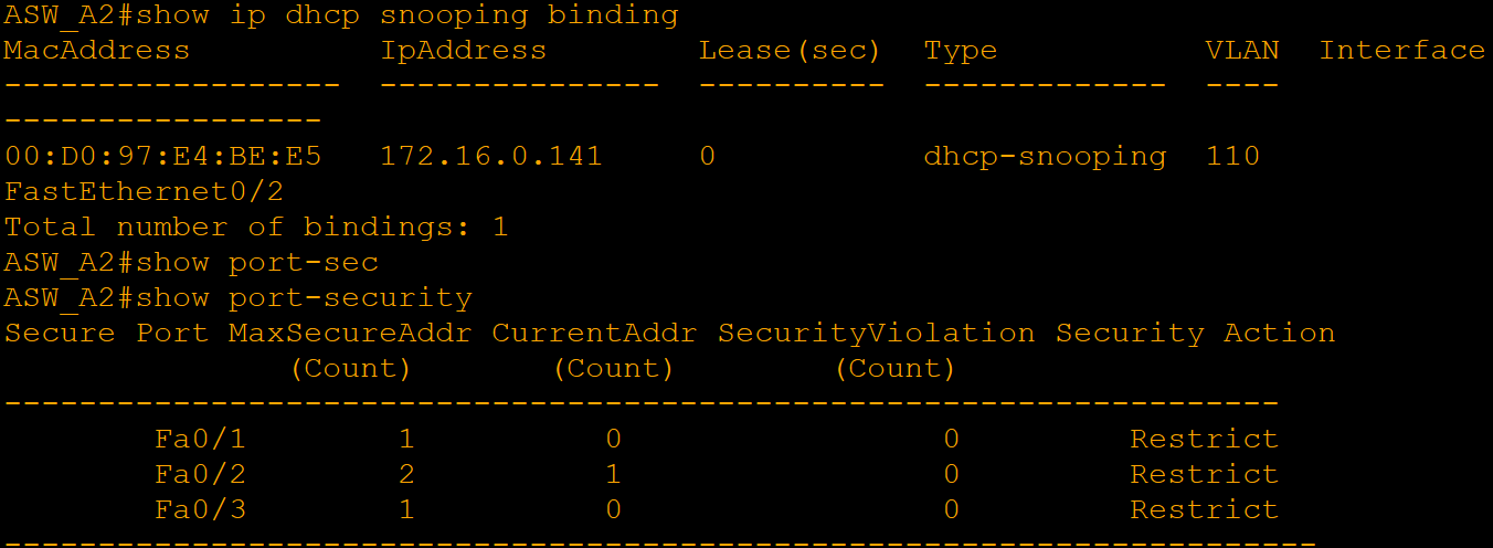
ACLs work at layer 3 and are based on the assumption that the frame carrying the packet is valid. We need to protect our ports too. Port security restricts the list of MAC addresses accepted by the port, DHCP snooping ensures that a rogue server cannot distribute IP addresses and keeps track of the lease for each port, and Dynamic ARP Inspection verifies all ARP messages on an untrusted port against this database. All three work on Access switches for all VLANs active, but only uplinks to Distribution switches are trusted.
Port security stores the known addresses in the running configuration, which ensures that the addresses stay on the same list across reboots and logs the violations without taking the port offline. It means that an unauthorized device will not be able to take down a legitimate one. As far as ports connected to an IP phone are concerned, they are allowed to have multiple addresses because the phone and the PC connected to it will appear in the same port. Also, DHCP snooping applies a rate limit to untrusted ports to ensure that there is no overflow in the address pool due to the flood of requests, and the limit on access point ports is set even higher because all the wireless clients on the AP send DHCP requests via the port.
There is one issue that needs explanation. Printers and the wireless controllers use static addresses, and therefore are not included in the snooping table and the inspection drops their ARP packets. On a real deployment, one would create an ARP ACL and add their addresses and MAC addresses into it. In this particular topology, those ports will be trusted for inspection, while port security holds their addresses down instead.
Part 8 - Wireless
Wireless
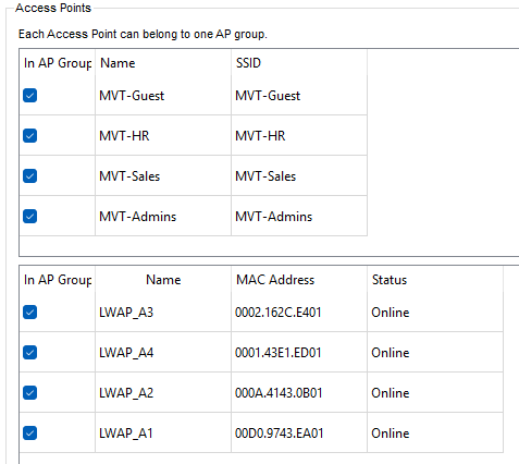
Each office has a Wireless LAN Controller in its IDF and one lightweight access point per department. The controller holds the WLANs and pushes them to the APs, so every SSID is configured once per office instead of on each AP.
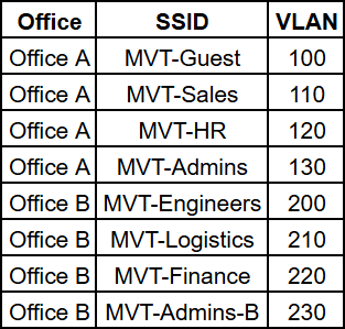
All WLANs use WPA2-PSK with AES. The guest SSID has its own passphrase, so visitors never learn the one used by staff.
The APs don’t have a fixed address. Packet Tracer’s lightweight AP only takes its address from DHCP, so each office has a pool in its Management VLAN, and that pool’s WLC Address field tells the AP where its controller is. After that the AP registers with the controller on its own and downloads the WLANs.
In a campus that has its own controller, WLANs normally use central switching. The AP tunnels client traffic back to the controller, and the controller puts it on the right VLAN. I set it up that way first, but Packet Tracer’s controller does not tag client traffic in this mode. Every client landed in the Management VLAN and took an address from the AP pool, which the MAC address table on the controller’s switch port confirmed. So the WLANs use local switching (FlexConnect) instead. The AP tags the traffic itself and hands it to its own Access switch, which is why the AP ports are trunks that carry the department VLAN plus the Management VLAN as native, and the controller’s trunk only needs the Management VLAN. FlexConnect is normally the choice for branch offices without a local controller; here it works around the simulator.
Every AP broadcasts every SSID of its office. Packet Tracer ignores custom AP groups, so an SSID can’t be tied to a single AP. This doesn’t affect the design, because the SSID, not the AP, decides which VLAN a client ends up in. A guest phone that joins through the Sales AP still lands in VLAN 100.
Which AP a client joins depends on distance, and that comes from the Physical view. The coverage range of every AP is 25 meters, a realistic cell size for an office, and each AP sits in its department’s room, so clients join the AP of their own room. Once connected, every client leases an address from its department’s pool, and the ACLs from Part 7 apply to wireless clients the same way they apply to wired ones.
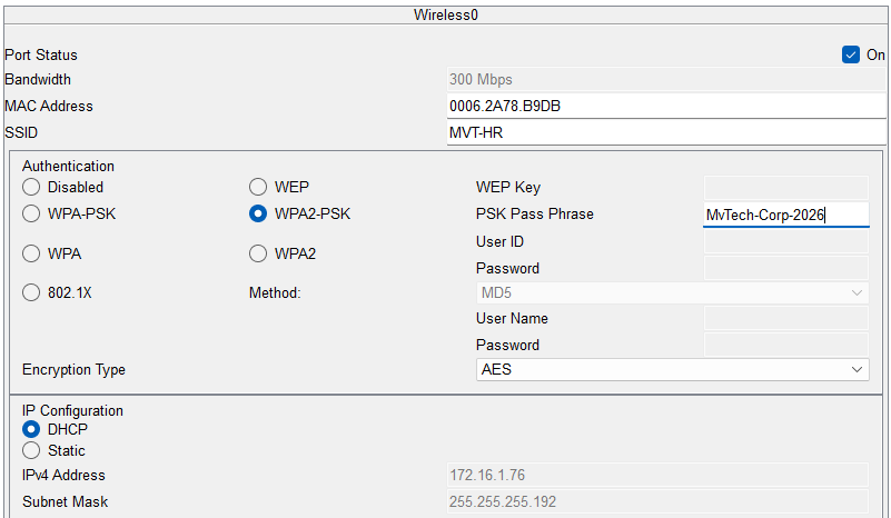
The guest phone reaches the company website but not the internal servers, and corporate laptops can’t open YouTube.
Part 9 - Physical Topology
The table below shows which room each device sits in.
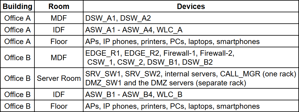
Office A - Main Distribution Frame
Office A’s MDF holds the two Distribution switches. Their uplinks to the core in Office B run over fiber, since that is where the aggregated traffic of the whole building flows.
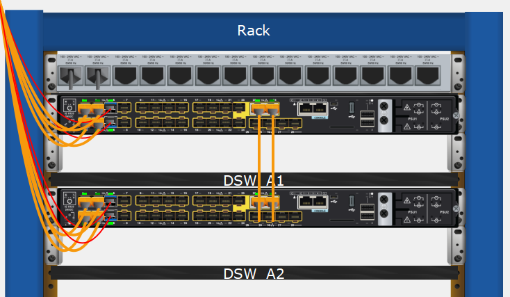
Office A - Intermediate Distribution Frame
The Access switches and WLC_A sit in the IDF, not next to the desks. Cables run from the wall outlets to a patch panel in the IDF, which keeps the switches in a locked room with power and cooling. The only limit is the 100-meter reach of copper.
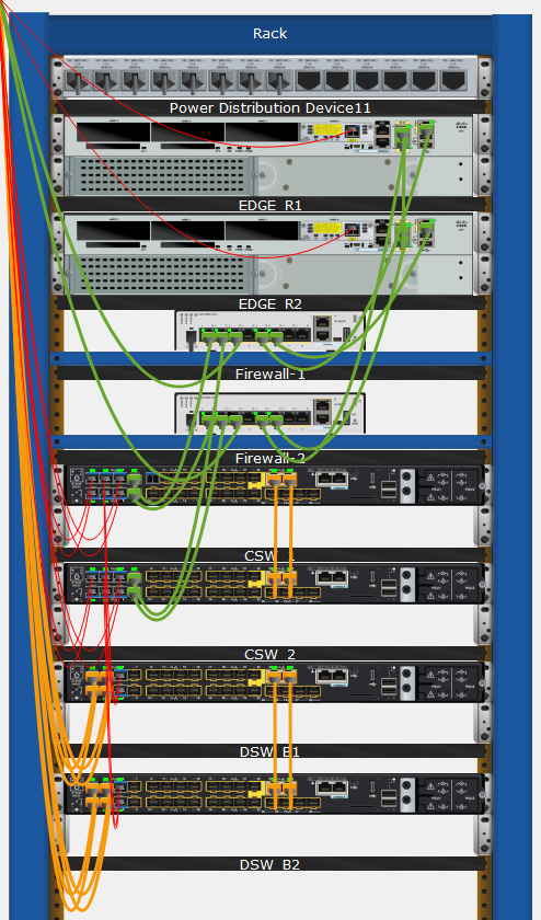
Office B - Main Distribution Frame
Office B’s MDF holds the edge routers, the firewalls, the core switches and Office B’s Distribution switches. Devices sharing this rack use copper patch cables, which is enough there since only traffic to the DMZ and the Internet crosses the firewall and the ISP link sets its limit. Packet Tracer’s ASA also only has copper ports.
The two ISPs sit in separate buildings and reach the site from different directions. Two providers only add redundancy if their cables don’t share a path, otherwise a single excavation can cut both.
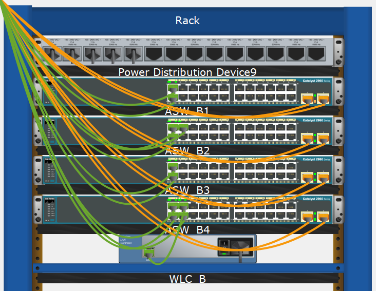
Office B - Intermediate Distribution Frame
The same layout as Office A, with ASW_B1 - ASW_B4 and WLC_B.
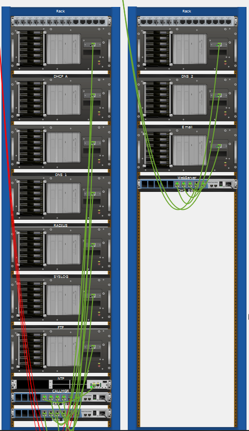
Office B - Server Room
The DMZ and the internal servers share a room but not a rack, so the separation the firewall enforces is visible on the physical side as well. The server switch uplinks to the core run over fiber.
Conclusion
In this project, I designed and simulated a real enterprise network as far as Packet Tracer allowed me. I built each part the way it would be built in a real network and explained the reasoning behind every decision.
At the start of the project, I didn’t expect Packet Tracer’s limitations to come up this often. Each time a feature didn’t work the way it would on real IOS, I had to find another way to reach the same result, which taught me the solutions I wouldn’t have looked for otherwise. At the same time, these limitations also restricted how far the design could go in Packet Tracer. That’s why I’m planning to build my future projects in GNS3. Even though building a project like this in GNS3 is more costly, it runs real device images, which will let me design a larger and more complex network.